Introduction
Physical electronic access control, almost always, involves driving an electromagnetic locking device of some sort. It might be a powerful magnet or a smaller solenoid within a strike or bolt. All these devices are subject to the same basic laws of physics. The electromagnet will store energy when powered and will generate a “back EMF”, or counter EMF (CEMF), when the supply is switched off.
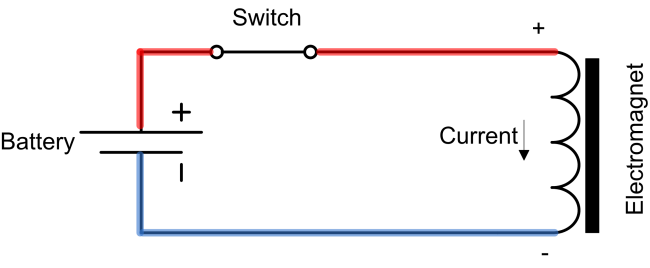
When the supply is connected current is flowing through the windings of the electromagnet coil. The final resting current is determined by the DC resistance of the coil winding and connecting wires. This current produces a magnetising field which aligns the magnetic domains in the metal core of the electromagnet. This alignment re-enforces the field making magnetic force greater but also storing a lot more energy in the process.
When the supply is switched off, the magnetic field will tend to collapse and in doing so will generate an EMF or (CEMF) in the electromagnet coil windings.
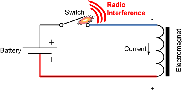
If this back EMF is not controlled or suppressed it will generate very large voltages that in turn can:
- Cause arcing at contacts, reducing switch life
- Generate interference
- Damage electronics
- Cause loss of data
EMF is an acronym for Electro-Motive Force. The term is slightly misleading as EMF is not, in fact, a force. It’s the voltage produced by the interaction of current in the coil of the electromagnet its magnetic field, when one, or both, is changing. The disconnected electromagnet acts like a current source; building whatever voltage is necessary to keep the original current flowing.
Back EMF Suppression
Back EMF cannot be prevented but it can be controlled. In suppressing the back EMF the objective is to prevent the very high voltages and dissipate the stored energy in a controlled way. There are a number of ways to do this and we will look at the two most common methods used in access control.
Flywheel Diode
The term “fly wheel” is very apt. The current flowing in an electromagnet is very much like a free spinning bicycle wheel. When the pedal is stopped (the supply voltage turned off) the wheel keeps turning.
The fly wheel diode provides a means of applying a brake to the fly wheel, When the supply voltage is connected the diode is reversed biased and is effectively out of circuit. When the switch opens fly wheel current produces a back EMF in the opposite polarity and so the diode will conduct. The diode does a very good job of suppressing the back EMF and clamps the voltage to around a one volt or so. This is quite suitable for small solenoids like those found in strikes. However these are not suitable for door magnets.

![]()
Why diodes are not suitable for magnets
The power dissipated by the diode is low because the forward volt drop is less than a volt. Thus the rate of energy removal from the electromagnet is low (Energy ≈ Power x Time) Thus:
![]()
So a smaller the power loss via the diode will mean a greater the time to dissipate the energy. The net result is the current keeps flowing and the magnet holds on to the armature for longer. This can be for as much as one to two seconds, leading to frustrating delayed door release.
Why MOVs are suitable for magnets and strikes
The MOV (VDR) has a rated voltage. Below this voltage it has a very high resistance. So by selecting a MOV with a rated voltage slightly higher than the normal supply voltage it may be safely connected across the coil of the magnet and just like the diode has no affect while the supply is connected.
Metal Oxide Varistor (MOV)
When the supply is disconnected, the Back EMF will rise to the rated voltage of the MOV. At this point the MOV will start to conduct and clamp the voltage to just above this value.


When clamping the back EMF, the voltage drop will typically be in the order of 30V or so. Using the same equation:
![]()
The power loss will be 30 times that of the diode. The net result being that the energy is lost approximately 30 times quicker, and the magnet releases the armature in much less time.
VDR’s suitable for 12 or 24 Volt Locks can be purchased from Distribution, quote product code 0043 (pack of 20).
See also: Counter-electromotive Force